Lab 12: Inverted Pendulum (Wheelie)
Overview
For this final lab we got the robot to balance on two wheels in the inverted pendulum configuration. We went with starting the car in the upright position and using a closed-loop PID controller to stabilize it around the balance point. The controller reads the pitch angle from the IMU gyroscope and drives the motors forward or backward to keep the robot from falling over. We did not attempt the flip-into-wheelie approach since getting the balance controller working on its own was challenging enough.
We decided to work in a group consisting of me, Rajarshi (rd496), and Clarence (cod8). Rajarshi designed the initial code architecture and provided the robot, I handled the Jupyter notebook integration for remote gain tuning and data logging, and Clarence did the physical testing with Rajarshi's help.
Approach
We considered both options from the lab spec: stabilize from upright, or drive forward and flip into a wheelie. We went with stabilize from upright because it let us isolate the balance controller without also needing to nail the flip timing. The proceedure is simple: one person holds the robot upright, someone runs the BALANCE cell in the notebook (which gives a 3-second countdown), and then you let go. The firmware zeroes the pitch at the moment the command arrives, so whatever orientation the robot is in becomes "0 degrees" and the controller tries to keep it there.
Controller Design
Pitch PID
The balance controller is a PID controller on the integrated pitch angle. It lives in runPitchPID() in pid.cpp and runs as pid_mode == 2. Each loop iteration it reads the IMU, integrates gyrY() to get the current pitch angle, computes the error relative to the setpoint (0 degrees), and outputs a motor command.
// Integrate gyro for pitch
unsigned long now_us = micros();
float dt = (now_us - prev_orient_time_us) / 1000000.0;
if (dt > 0 && dt < 0.1) {
    pitch_g += myICM.gyrY() * dt;
}

float error = pid_setpoint - pitch_g;

// P term
float p_term = kp * error;

// I term with anti-windup
i_term += error * ki * dt;
i_term = constrain(i_term, -300, 300);

// D term: use raw gyrY() directly (pitch angular rate)
float gyro_rate = myICM.gyrY();
float d_term = kd * (-gyro_rate);
if (abs(d_term) < 1.0) d_term = 0;  // LPF threshold

float raw_output = p_term + i_term + d_term;
int motor_cmd = constrain((int)raw_output, -255, 255);

// Brake if fallen or at target
if ((abs(error) <= 2.5) || (abs(error) >= 87.5)) {
    brakeMotors();
}
The P term pushes the robot back toward upright when it tilts. The D term uses the raw gyro rate directly rather than differentiating the error numerically, which gives a cleaner derivative signal with less noise. A small LPF threshold zeros out tiny D values to reduce motor chatter. When the motor command is positive the robot drives forward; when negative it drives backward. There's a small deadband so the motors don't buzz at tiny error values, and a brake zone within 2.5 degrees of the setpoint. The controller also brakes if the error exceeds 87.5 degrees, which means the robot has fallen and there's no point fighting it.
We initially kept Ki at zero to simplify tuning, but found that adding a small integral term (Ki = 0.8) helped the controller correct for persistent lean. The I term has anti-windup clamping at ±300 so it doesn't blow up if the robot falls over.
Gain Tuning
Gains are sent over BLE using SET_PID_GAINS so we could tune without reflashing. We did 20+ runs to find gains that worked. With low Kp values the robot just fell over on the first tilt; it couldn't react fast enough to catch itself. There was no oscillation at all with bad gains, just an immediate fall. We gradually increased Kp until the robot could actually push back against a tilt, then added Kd to damp the corrections and stop it from overreacting.
Our final gains on carpet were Kp = 12.25, Ki = 0.8, Kd = 0.75. The extra friction from the carpet helped the wheels grip which made tuning easier.
We also lost a few runs to a bug where Clarence had the D term reading gyrZ() instead of gyrY() for the derivative. Since that's the wrong axis entirely, the D term was responding to rotation the controller didn't care about and ignoring the rotation it did. Once we caught that and switched to the correct axis the controller started actually damping the oscillations like it was supposed to.
The Math
An inverted pendulum is inherently unstable. If the robot tilts by some angle θ from vertical, gravity exerts a torque proportional to sin(θ) that pulls it further away from upright. For small angles sin(θ) ≈ θ, so the linearized equation of motion looks like θ̈ = (g/L)θ - (1/L)u, where g is gravity, L is the effective pendulum length (roughly the distance from the wheel axle to the center of mass), and u is the corrective acceleration provided by the wheels. Without any control input the system diverges exponentially; the controller's job is to apply u fast enough to counteract the gravitational torque before θ gets too large.
Our PID controller computes the motor command as u = Kp·e + Ki·∫e + Kd·(de/dt), where e = (0 - θ) is the error between the setpoint and the current pitch. The proportional term Kp·e provides a restoring force that pushes the robot back toward vertical whenever it tilts. On its own this would cause the robot to oscillate around the setpoint since it has no way to anticipate when it's approaching zero and should start slowing down. The derivative term Kd·(de/dt) handles that by opposing the rate of change of the error; as the robot swings back toward upright the derivative term applies a braking force that prevents overshoot. The integral term accumulates error over time and corrects for persistent lean. Together these terms act like a spring (P), a damper (D), and a slow corrector (I).
The reason we read the gyro rate directly for the D term instead of numerically differentiating the pitch angle is noise. Taking the discrete derivative of a signal amplifies high-frequency noise, so you'd need a low-pass filter on top of it. The gyro already gives us the angular rate as a clean analog measurement so we can skip that entirely and just use it directly. This is a standard trick in PID implementations on real hardware.
The linearization (sin(θ) ≈ θ) breaks down at larger angles, which is consistent with what we saw in testing. Within about 10 degrees the small-angle assumption holds and the controller behaves predictably. Past that the actual gravitational torque grows faster than the linear model predicts, so the controller underestimates how hard it needs to push back and can't recover. A gain-scheduled controller that increases Kp at larger angles could help with this, but we didn't implement one.
Jupyter Integration
The notebook (balance_run.ipynb) handles the full workflow over BLE: set gains, send the BALANCE command with a 3-second countdown so you can position the robot, wait for the run to finish (the firmware has a 10-second timeout), then pull the logged data back with GET_PID_LOG. Each log line contains a timestamp, the pitch angle, and the motor command. The notebook parses these into a DataFrame and generates pitch/motor plots and error statistics.
# Set gains remotely
KP, KI, KD = 12.25, 0.8, 0.75
ble.send_command(CMD.SET_PID_GAINS, f"{KP}|{KI}|{KD}")

# Countdown then start
for i in range(3, 0, -1):
    print(f"Starting balance in {i} ...")
    time.sleep(1.0)
ble.send_command(CMD.BALANCE, "0")
One thing we had to fix in the firmware: the GET_PID_LOG handler in commands.cpp was sending pid_yaw_array for all non-position modes, but the balance controller writes to pid_pitch_array. We added a check for pid_mode == 2 so it sends the correct array.
BLE Challenges
Getting BLE working took longer than expected since we were working in a group and everyone had different coding styles. On top of that, Rajarshi's robot had some wierd issue where it would disconnect right after we tried to start a run. We eventually got it stable but it ate into our testing time. Still worth it to use his robot though because it wasn't the only one 90% mounted via tape.
Results
Videos
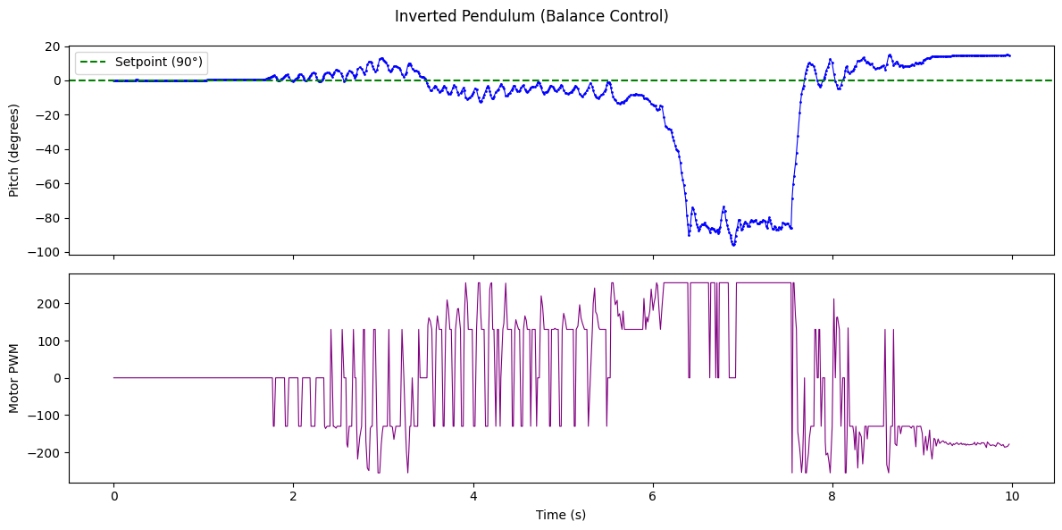
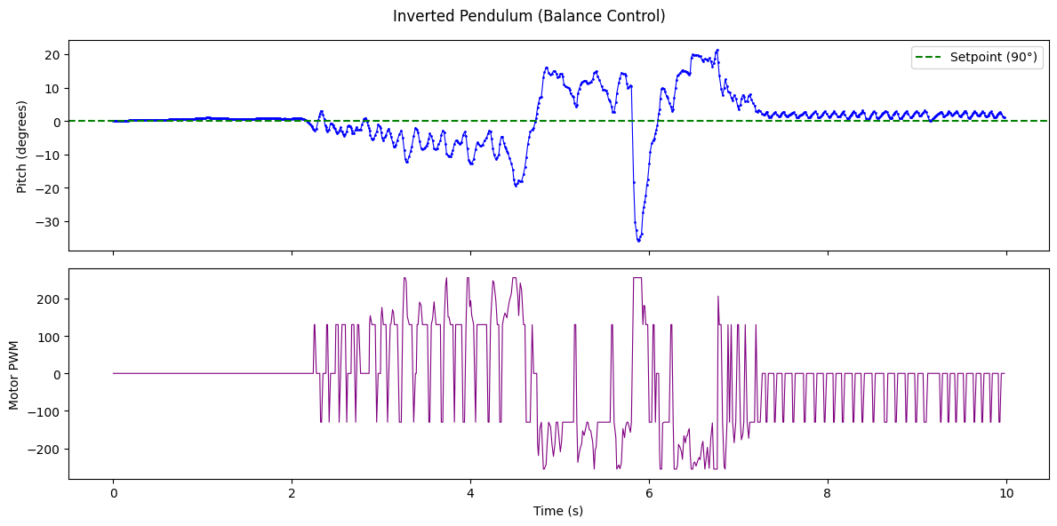
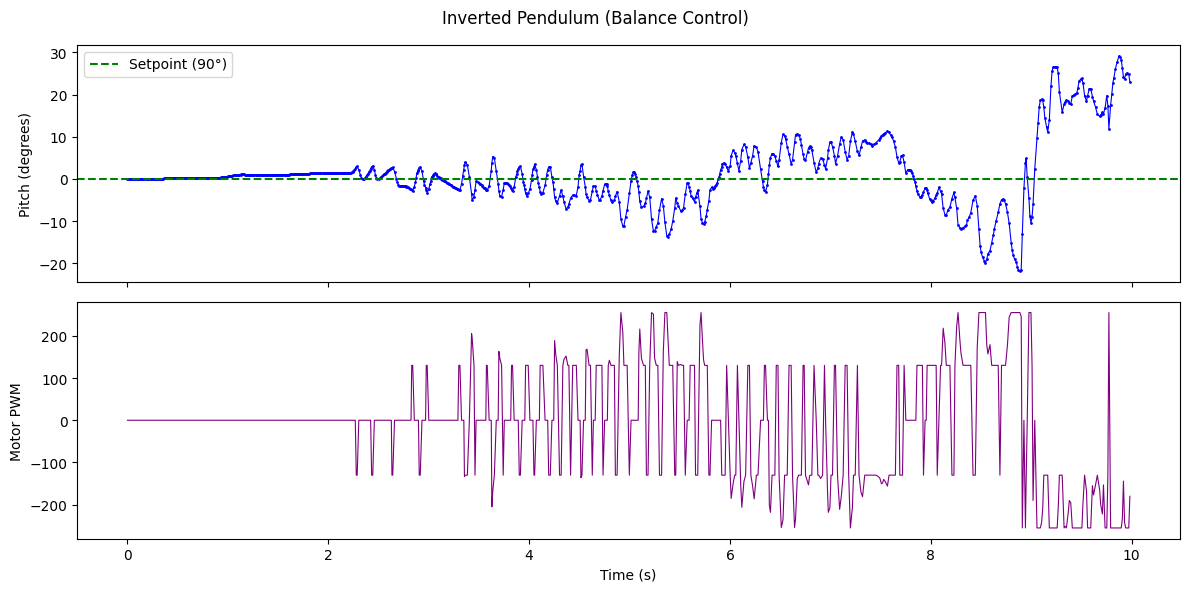
The robot stayed upright with some visible twitching as the controller made small corrections back and forth. The controller was actually really good at holding position within about 10 degrees of upright; the corrections in that range were quick and consistent. But once it tilted past that band the recovery got much less reliable, and eventually the robot tipped too far to the left and couldn't come back. This was a consistent failure mode; when it fell it almost always went to the left, which suggests there might be a slight mechanical asymmetry in the chassis or wheel friction, or a small bias in the gyro that accumulated over time. Or maybe just because we're all right hand dominant we held it tilted wrong at the beginning.
Trial 1: Pitch and Motor Output
Trial 2: Pitch and Motor Output
Trial 3: Pitch and Motor Output
Discussion
The balancing is far from perfect but it does demonstrate that the controller works. The main limitation is gyro drift; since we're integrating the gyro rate to get pitch, any bias accumulates over time and slowly shifts what the controller thinks "upright" is. A complementary filter combining the gyro with accelerometer data could help, though we didn't have time to implement one.
Collaborations: Rajarshi (robot and initial code architecture), Clarence (testing with Rajarshi's help), I handled the Jupyter integration for remote tuning and data logging. Claude assisted with the notebook structure and report.